State transition testing is used where some aspect of the system can be described in what is called a ‘finite state machine’. This simply means that the system can be in a (finite) number of different states, and the transitions from one state to another are determined by the rules of the ‘machine’. This is the model on which the system and the tests are based.
- Any system where you get a different output for the same input, depending on what has happened before, is a finite state system.
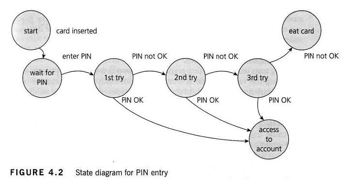
- A finite state system is often shown as a state diagram (see Figure 4.2).
- One of the advantages of the state transition technique is that the model can be as detailed or as abstract as you need it to be. Where a part of the system is more important (that is, requires more testing) a greater depth of detail can be modeled. Where the system is less important (requires less testing), the model can use a single state to signify what would otherwise be a series of different states.
- A state transition model has four basic parts:
- The states that the software may occupy (open/closed or funded/insufficient funds);
- The transitions from one state to another (not all transitions are allowed);
- The events that cause a transition (closing a file or withdrawing money);
- The actions that result from a transition (an error message or being given your cash).
 Hence we can see that in any given state, one event can cause only one action, but that the same event – from a different state – may cause a different action and a different end state.
For example, if you request to withdraw $100 from a bank ATM, you may be given cash. Later you may make exactly the same request but it may refuse to give you the money because of your insufficient balance.
This later refusal is because the state of your bank account has changed from having sufficient funds to cover the withdrawal to having insufficient funds. The transaction that caused your account to change its state was probably the earlier withdrawal.
A state diagram can represent a model from the point of view of the system, the account or the customer.
Let us consider another example of a word processor. If a document is open, you are able to close it. If no document is open, then ‘Close’ is not available. After you choose ‘Close’ once, you cannot choose it again for the same document unless you open that document. A document thus has two states: open and closed.
We will look first at test cases that execute valid state transitions.
Figure 4.2 below, shows an example of entering a Personal Identity Number (PIN) to a bank account. The states are shown as circles, the transitions as lines with arrows and the events as the text near the transitions. (We have not shown the actions explicitly on this diagram, but they would be a message to the customer saying things such as ‘Please enter your PIN’.)
The state diagram shows seven states but only four possible events (Card inserted, Enter PIN, PIN OK and PIN not OK). We have not specified all of the possible transitions here – there would also be a time-out from ‘wait for PIN’ and from the three tries which would go back to the start state after the time had elapsed and would probably eject the card.
There would also be a transition from the ‘eat card’ state back to the start state. We have not specified all the possible events either – there would be a ‘cancel’ option from ‘wait for PIN’ and from the three tries, which would also go back to the start state and eject the card.
In deriving test cases, we may start with a typical scenario.
- First test case here would be the normal situation, where the correct PIN is entered the first time.
- A second test (to visit every state) would be to enter an incorrect PIN each time, so that the system eats the card.
- A third test we can do where the PIN was incorrect the first time but OK the second time, and another test where the PIN was correct on the third try. These tests are probably less important than the first two.
- Note that a transition does not need to change to a different state (although all of the transitions shown above do go to a different state). So there could be a transition from ‘access account’ which just goes back to ‘access account’ for an action such as ‘request balance’.
Test conditions can be derived from the state graph in various ways. Each state can be noted as a test condition, as can each transition. However this state diagram, even though it is incomplete, still gives us information on which to design some useful tests and to explain the state transition technique.
We need to be able to identify the coverage of a set of tests in terms of transitions. We can also consider transition pairs and triples and so on.
Coverage of all individual transitions is also known as 0-switch coverage, coverage of transition pairs is l-switch coverage, coverage of transition triples is 2-switch coverage, etc. Deriving test cases from the state transition model is a black-box approach.
Measuring how much we have tested (covered) will discuss in a white-box perspective. However, state transition testing is regarded as a black-box technique.
Other popular articles:
- Where to apply this test coverage in software testing?
- What are the types of coverage?
- What is Use case testing in software testing?
- What is a Defect Life Cycle or a Bug lifecycle in software testing?
- How to choose that which testing technique is best?

Taghreed Anany says
We need more info about 0- switch and 1-switch and 2-switch
jahar says
good info